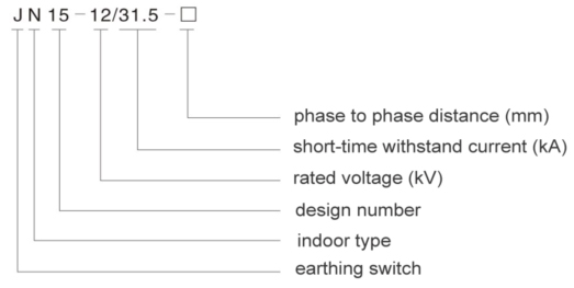
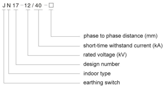
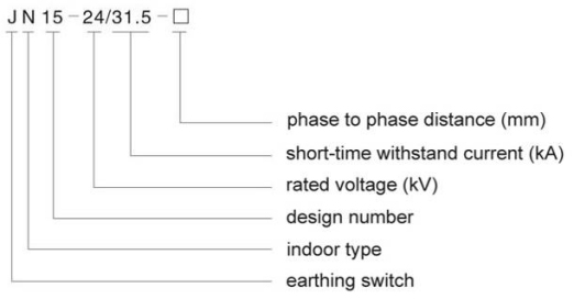
Earthing Switch
12kV Earthing Switch JN15-12(M)/31.5
1. Product Overview
 |
 |


2. Primary Parameters
2.1 Rated working voltage 12kV
2.2 Rated short-time withstand current 31.5kA
2.3 Rated short-circuit withstand time 4S
2.4 Rated peak withstand current 80kA
2.5 Rated short-circuit making current 80kA
2.6 Insulation level:
Short-time power frequency withstand voltage 42kV
Lightning impulse withstand voltage 75kV
2.7 Operating mechanical lifespan 2000times
3. Environment Conditions
3.1 Application altitude: ≤ 1000 meters;
3.2 Environmental temperature: ≤ +40℃, ≥ -25℃;
3.3 Daily average relative humidity: ≤ 95%; monthly average relative humidity ≤ 90%;
3.4 Earthquake intensity: ≤ 8 degree;
3.5 Filthy degree: ≤ II degree.
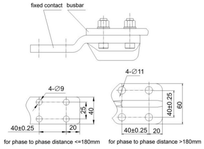
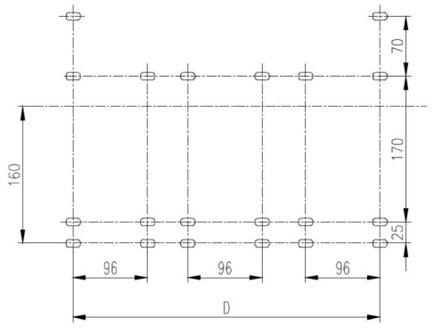
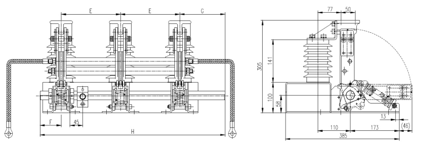
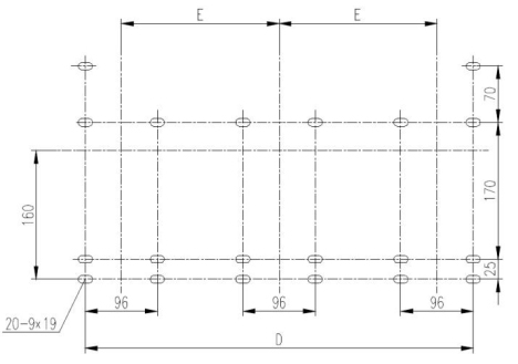
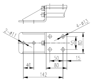
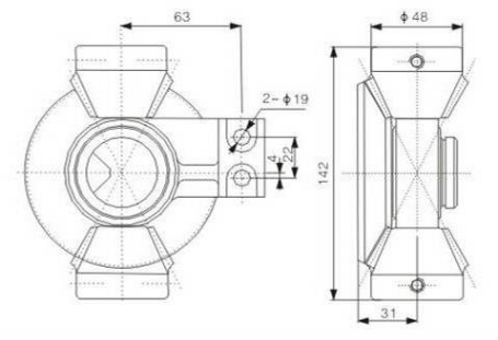
4. Dimensional Drawing for JN15-12/31.5
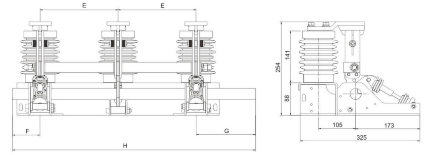

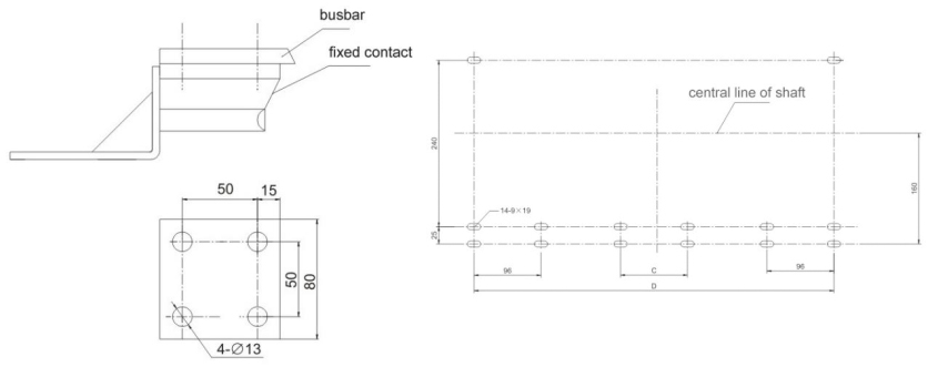
| Wiring Terminals | Mounting Holes |
 |
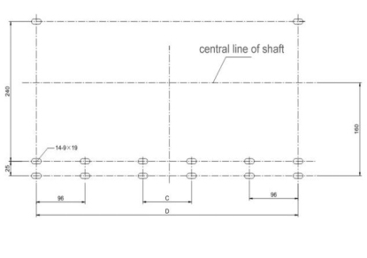 |
Unit: mm
|
Model |
E |
F |
G |
H |
D |
C |
|
JN15-12/31.5-150 |
150 |
75 |
140 |
515 |
396.5 |
|
|
JN15-12/31.5-165 |
165 |
75 |
160 |
565 |
426 |
|
|
JN15-12/31.5-180 |
180 |
75 |
160 |
595 |
456 |
|
|
JN15-12/31.5-200 |
200 |
75 |
160 |
635 |
496 |
|
|
JN15-12/31.5-210 |
210 |
75 |
160 |
655 |
516 |
|
|
JN15-12/31.5-220 |
220 |
75 |
160 |
675 |
536 |
|
|
JN15-12/31.5-230 |
230 |
75 |
160 |
695 |
556 |
96 |
|
JN15-12/31.5-250 |
250 |
75 |
160 |
735 |
596 |
96 |
|
JN15-12/31.5-275 |
275 |
75 |
185 |
810 |
646 |
96 |
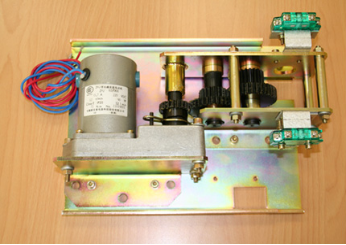
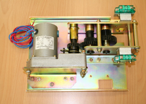
5. Motorized Earthing Switch JN15-12M/31.5
Motors and Gears for Motorized Earthing Switch JN15-12M/31.5, “M” indicates motorized type, without “M” indicates manual type.
 |
|


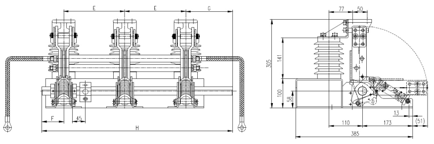
6. Dimensional Drawing for JN15-12M/31.5-150

|
|
|


Unit: mm
|
Model |
E |
F |
G |
H |
D |
|
JN15-12M/31.5-150 |
150 |
75 |
140 |
515 |
396.5 |
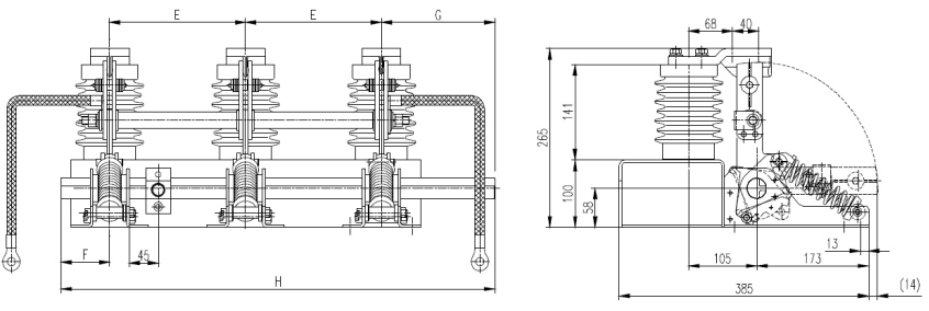
7. Dimensional Drawing for JN15-12M/31.5-210(275)
|
Model |
E |
F |
G |
H |
D |
|
JN15-12M/31.5-210 |
210 |
75 |
160 |
665 |
516 |
|
JN15-12M/31.5-275 |
275 |
75 |
185 |
810 |
646 |
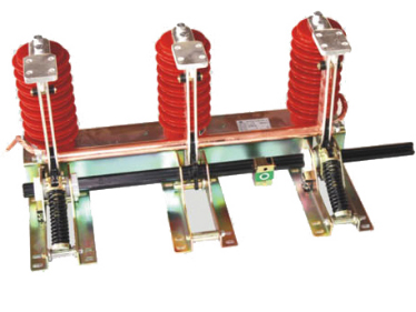
Earthing Switch JN17-12(M)/40(50)
12kV Earthing Switch JN17-12(M)/40(50)
1. Product Overview
 |
 |


2. Primary Parameters
2.1 Rated working voltage 12kV
2.2 Rated short-time withstand current 40kA/50kA
2.3 Rated short-circuit withstand time 4S
2.4 Rated peak withstand current 100kA/125kA
2.5 Rated short-circuit making current 100kA/125kA
2.6 Insulation level:
Short-time power frequency withstand voltage 42kV
Lightning impulse withstand voltage 75kV
2.7 Operating mechanical lifespan 2000times
3. Environment Conditions
3.1 Application altitude: ≤ 1000 meters;
3.2 Environmental temperature: ≤ +40℃, ≥ -10℃;
3.3 Daily average relative humidity: ≤ 95%; monthly average relative humidity ≤ 90%;
3.4 Earthquake intensity: ≤ 8 degree;
3.5 Filthy degree: ≤ II degree.
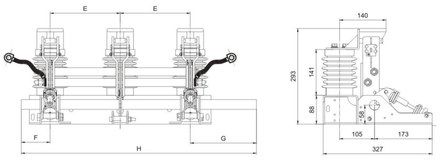
4. Dimensional Drawing for JN17-12/40
|
Wiring Terminals |
Mounting Holes |
|
|
|

Unit (mm)
|
Model |
E |
F |
G |
H |
D |
|
JN17-12/40-210 |
210 |
50 |
185 |
655 |
516 |
|
JN17-12/40-220 |
220 |
50 |
185 |
675 |
536 |
|
JN17-12/40-230 |
220 |
50 |
185 |
695 |
556 |
|
JN17-12/40-250 |
250 |
50 |
185 |
735 |
596 |
|
JN17-12/40-275 |
275 |
50 |
210 |
810 |
646 |
5. Motorized Earthing Switch JN17-12M/40(50)
Motors and Gears for Motorized Earthing Switch JN17-12M/40(50), “M” indicates motorized type, without “M” indicates manual type.
|
|
|


6. Dimensional Drawing for JN17-12M/40-210(275)
 |
 |


Unit: mm
|
Model |
E |
F |
G |
H |
D |
|
JN17-12M/40-210 |
210 |
75 |
160 |
665 |
516 |
|
JN17-12M/40-275 |
275 |
75 |
185 |
810 |
646 |
7. Dimensional Drawing for JN17-12/50-210(275) & JN17-12M/50-210(275)
 |
 |
Unit: mm
|
Model |
E |
F |
G |
H |
D |
|
JN17-12(M)/50-210 |
210 |
75 |
160 |
665 |
516 |
|
JN17-12(M)/50-275 |
275 |
75 |
185 |
810 |
646 |
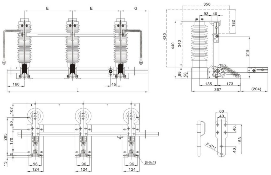
Earthing Switch JN15-24(M)/31.5
24kV Earthing Switch JN15-24(M)/31.5
1. Product Overview
|
|
|


2. Primary Parameters
2.1 Rated working voltage 24kV
2.2 Rated short-time withstand current 31.5kA
2.3 Rated short-circuit withstand time 4S
2.4 Rated peak withstand current 80kA
2.5 Rated short-circuit making current 80kA
2.6 Insulation level:
Short-time power frequency withstand voltage 65kV
Lightning impulse withstand voltage 95kV
2.7 Operating mechanical lifespan 2000times
3. Environment Conditions
3.1 Application altitude: ≤ 1000 meters;
3.2 Environmental temperature: ≤ +40℃, ≥ -10℃;
3.3 Daily average relative humidity: ≤ 95%;
3.4 Earthquake intensity: ≤ 8 degree;
3.5 Filthy degree: ≤ II degree.
4. Motorized Earthing Switch JN15-24M/31.5
Motors and Gears for Motorized Earthing Switch JN15-24M/31.5, “M” indicates motorized type, without “M” indicates manual type
 |
 |


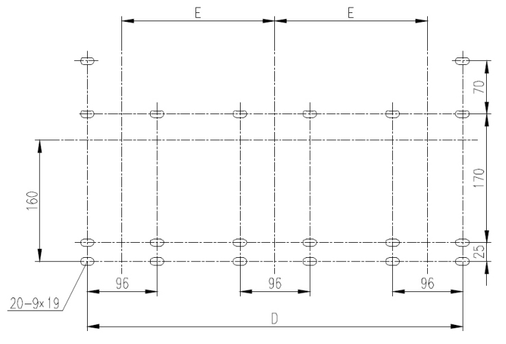
5. Dimensional Drawing for JN15-24/31.5 & JN15-24M/31.5
 |
 |

Unit: mm
|
Model |
E |
F |
G |
H |
D |
|
JN15-24(M)/31.5-210 |
210 |
75 |
160 |
665 |
516 |
|
JN15-24(M)/31.5-275 |
275 |
75 |
185 |
810 |
646 |
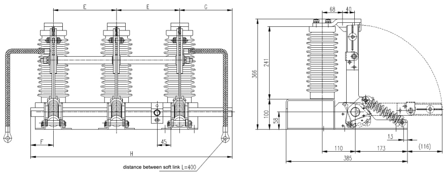
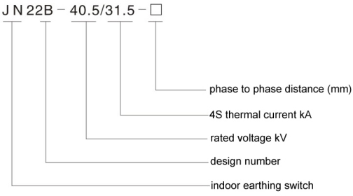
Earthing Switch JN22B-40.5(M)/31.5
40.5kV Earthing Switch JN22B-40.5(M)/31.5
1. Product Overview
 |
 |

2. Primary Parameters
2.1 Rated working voltage 40.5kV
2.2 Rated short-time withstand current 31.5kA
2.3 Rated short-circuit withstand time 4S
2.4 Rated peak withstand current 80kA
2.5 Rated short-circuit making current 80kA
2.6 Insulation level:
Short-time power frequency withstand voltage 95kV
Lightning impulse withstand voltage 185kV
2.7 Phase to phase distance 280/300/350/400mm
3. Environment Conditions
3.1 Application altitude: ≤ 1000 meters;
3.2 Environmental temperature: ≤ +40℃, ≥ -10℃;
3.3 Daily average relative humidity: ≤ 95%;
3.4 Earthquake intensity: ≤ 8 degree;
3.5 Filthy degree: ≤ II degree.
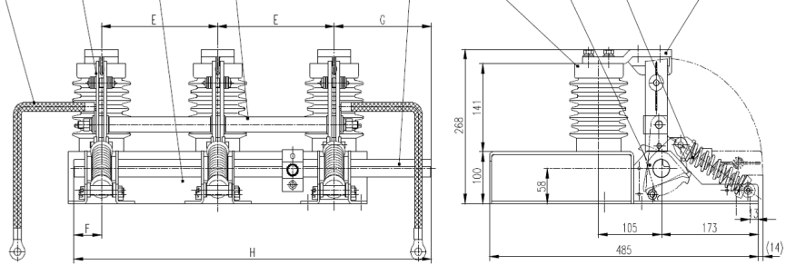
4. Dimensional Drawing for JN22B-40.5/31.5


Remark: insulation barrier will be added for phase to phase distance less than 360mm
Unit: mm
|
Model |
E |
G |
L |
D |
|
JN22B-40.5/31.5-280 |
280 |
290 |
1010 |
656 |
|
JN22B-40.5/31.5-300 |
300 |
340 |
1100 |
696 |
|
JN22B-40.5/31.5-350 |
350 |
340 |
1200 |
796 |
|
JN22B-40.5/31.5-360 |
360 |
320 |
1200 |
816 |
|
JN22B-40.5/31.5-400 |
400 |
340 |
1300 |
896 |
5. Motorized Earthing Switch JN22B-40.5M/31.5
Motors and Gears for Motorized Earthing Switch JN22B-40.5M/31.5, “M” indicates motorized type, without “M” indicates manual type.
|
|
|


6. Dimensional Drawing for JN22B-40.5M/31.5


 Remark: insulation barrier will be added for phase to phase distance less than 360mm
Unit: mm
|
Model |
E |
F |
|
JN22B-40.5M/31.5-280 |
280 |
290 |
|
JN22B-40.5M/31.5-300 |
300 |
340 |
|
JN22B-40.5M/31.5-350 |
350 |
340 |
|
JN22B-40.5M/31.5-360 |
360 |
320 |
|
JN22B-40.5M/31.5-400 |
400 |
340 |
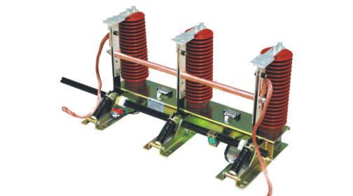
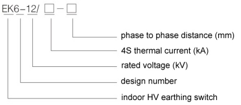
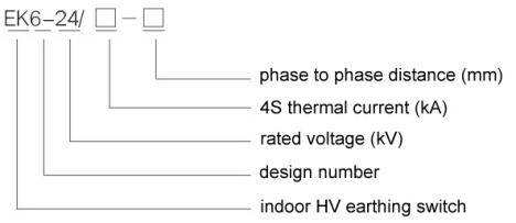
Earthing Switch EK6-12
12kV Earthing Switch EK6-12
1. Product Overview
 |
 |

2. Primary Parameters
2.1 Rated working voltage 12kV
2.2 Rated short-time withstand current 31.5kA/40kA
2.3 Rated short-circuit withstand time 4S
2.4 Rated peak withstand current 80kA/100kA
2.5 Rated short-circuit making current 80kA/100kA
2.6 Insulation level:
Short-time power frequency withstand voltage 42kV
Lightning impulse withstand voltage 75kV
2.7 Operating mechanical lifespan 2000times
3. Environment Conditions
3.1 Application altitude: ≤ 1000 meters;
3.2 Environmental temperature: ≤ +40℃, ≥ -10℃;
3.3 Daily average relative humidity: ≤ 95%; monthly average relative humidity ≤ 90%;
3.4 Earthquake intensity: ≤ 8 degree;
3.5 Filthy degree: ≤ II degree.
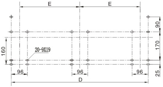
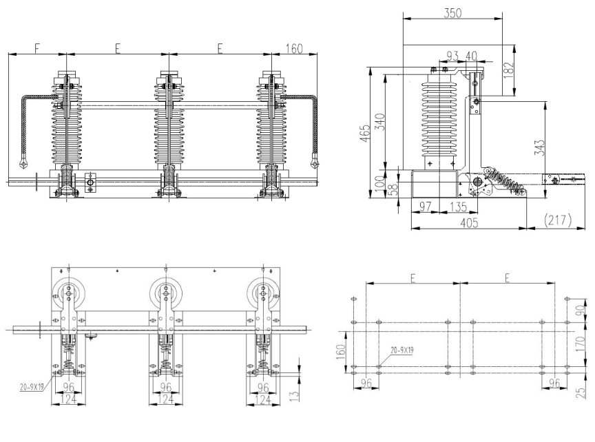
4. Dimensional Drawing for EK6-12
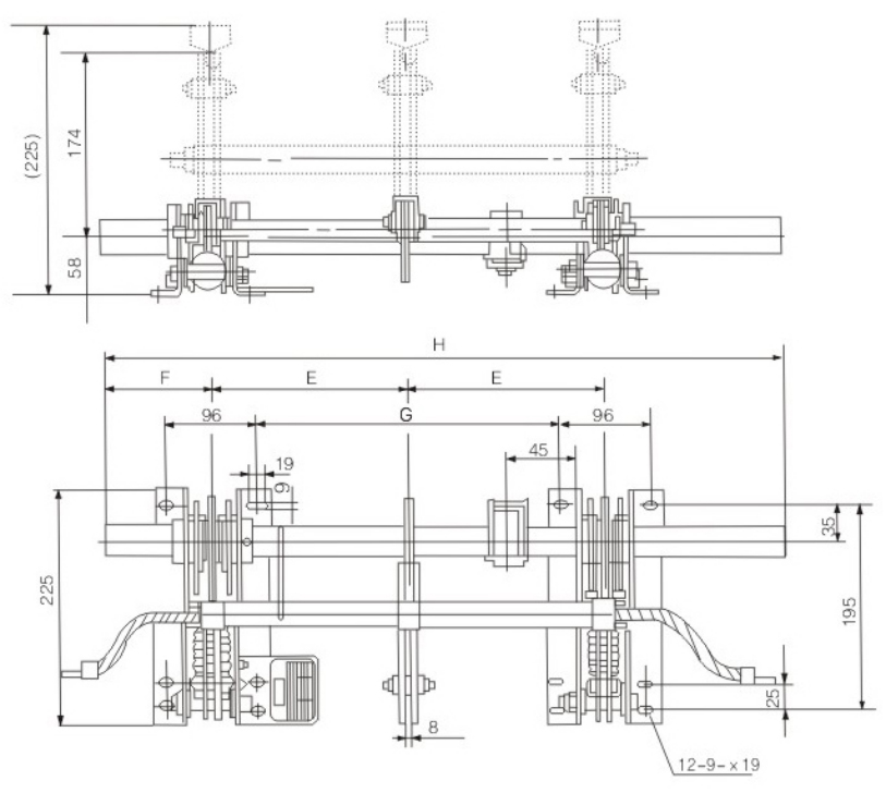
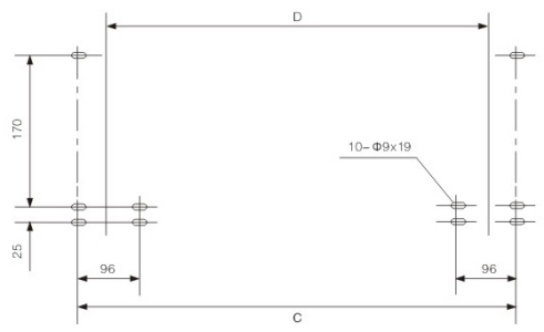

Unit: mm
|
Model |
E |
F |
G |
H |
C |
D |
|
EK6-12/31.5(40)-150 |
150 |
75 |
204 |
535 |
396 |
300 |
|
EK6-12/31.5(40)-210 |
210 |
50 |
324 |
655 |
516 |
420 |
|
EK6-12/31.5(40)-275 |
275 |
50 |
454 |
810 |
646 |
550 |
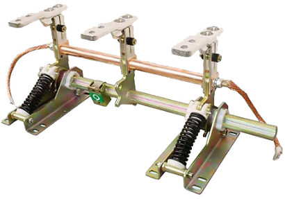
Earthing Switch EK6-24
24kV Earthing Switch EK6-24
1. Product Overview
|
|
|


2. Primary Parameters
2.1 Rated working voltage 24kV
2.2 Rated short-time withstand current 31.5kA
2.3 Rated short-circuit withstand time 4S
2.4 Rated peak withstand current 80kA
2.5 Rated short-circuit making current 80kA
2.6 Insulation level:
Short-time power frequency withstand voltage 65kV
Lightning impulse withstand voltage 95kV
2.7 Isolation gap after breaking not less than 125mm
3. Environment Conditions
3.1 Application altitude: ≤ 1000 meters;
3.2 Environmental temperature: ≤ +40℃, ≥ -10℃;
3.3 Daily average relative humidity: ≤ 95%; monthly average relative humidity ≤ 90%;
3.4 Earthquake intensity: ≤ 8 degree;
3.5 Filthy degree: ≤ II degree.
4. Dimensional Drawing for EK6-24/31.5

Unit: mm
|
Model |
E |
C |
L |
|
EK6-24/31.5-210 |
210 |
516 |
655 |
|
EK6-24/31.5-250 |
250 |
596 |
760 |
|
EK6-24/31.5-275 |
275 |
646 |
810 |
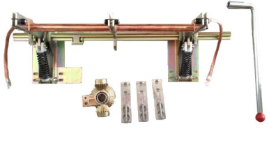
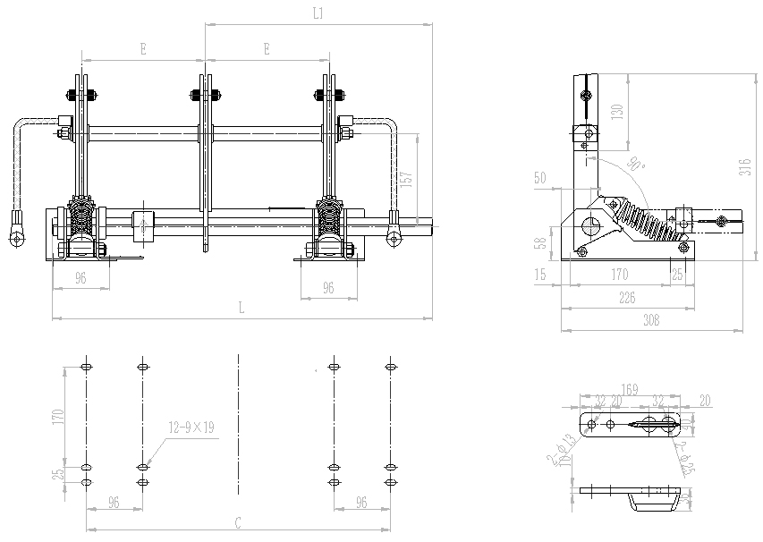
Earthing Switch Accessories
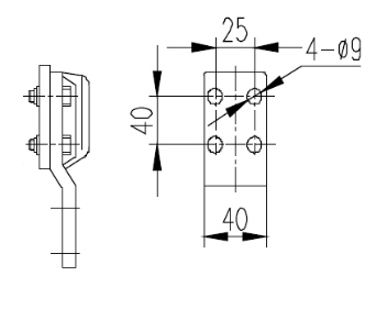
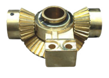
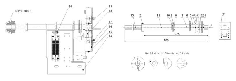
1. Bevel Gear Assembly (single-direction & double-direction types)
Single-direction Bevel Gear 5XS.245.001.1~4
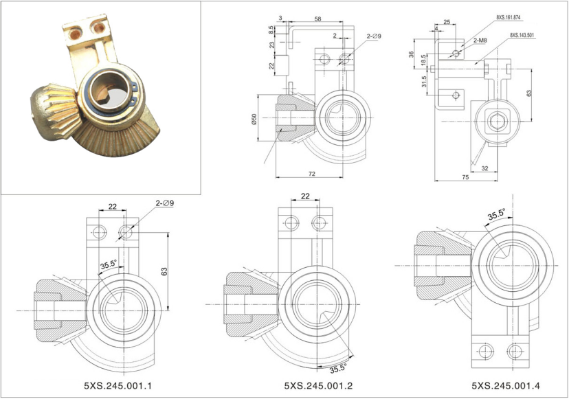

Double-direction Bevel Gear 5XS.245.002.1
 |
 |


2. Earthing Switch’s Interlocking Mechanism 5XS.363.010.1 (for elbow transmission)
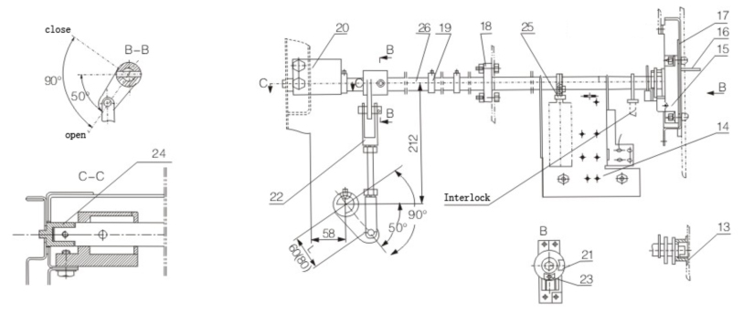

Parts of Interlock 5XS.363.010.1
|
Item |
Name of Part |
Code |
Qty/set |
|
1 |
Bearing |
8XS.263.011 |
1 |
|
2 |
Sector plate |
8XS.192.010 |
1 |
|
3 |
Sector plate |
8XS.192.011 |
1 |
|
4 |
Axial bush |
8XS.210.014.1 |
2 |
|
5 |
Sector plate |
8XS.151.041 |
1 |
|
6 |
Axial bush |
8XS.211.061 |
1 |
|
7 |
Sector plate |
8XS.151.039 |
1 |
|
8 |
Axial bush |
8XS.211.062 |
1 |
|
9 |
Screw |
GB70-85 |
1 |
|
10 |
Sector plate |
8XS.151.042 |
1 |
|
11 |
Sector plate |
8XS.151.043 |
1 |
|
12 |
Operating axis |
8XS.151.013 |
1 |
|
13 |
Cover |
8XS.017.011.1 |
1 |
|
14 |
Bend plate |
8XS.161.058 |
1 |
|
15 |
Support saddle |
5XS.043.022 |
1 |
|
16 |
Bend plate |
8XS.161.059 |
1 |
|
17 |
Slide block |
8XS.143.010 |
2 |
|
18 |
Bearing |
8XS.211.058 |
1 |
|
19 |
Stop collar |
8XS.211.057 |
3 |
|
20 |
Support saddle |
8XS.043.019 |
1 |
|
21 |
Closing indicator |
8XS.866.010 |
1 |
|
22 |
Connecting rod |
5XS.233.030 |
1 |
|
23 |
Opening indicator |
8XS.866.011 |
1 |
|
24 |
Lock tube |
8XS.211.059 |
1 |
|
25 |
Toothed flashboard |
8XS.151.044 |
1 |
|
26 |
Axial bush |
8XS.211.060 |
2 |
Earthing Switch Interlocking Mechanism 5XS.577.1001 (for single-direction bevel gear transmission)

Earthing Switch Interlocking Mechanism 5XS.577.1002 (for double-direction bevel gear transmission)
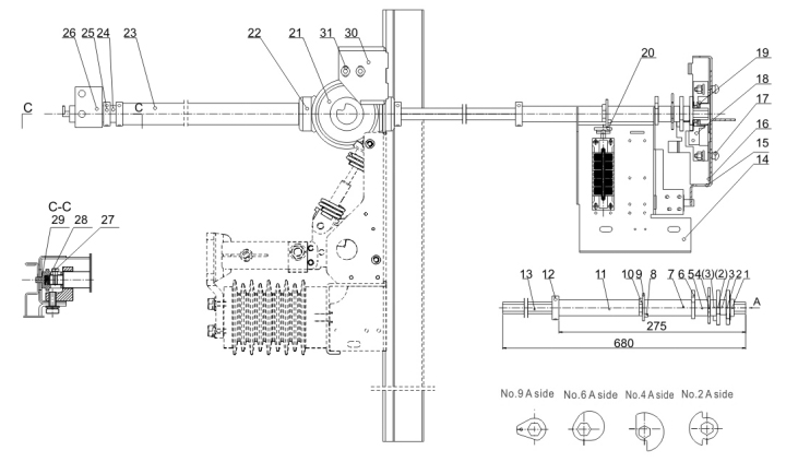

Parts of Interlock 5XS.577.1001/1002
|
No |
Name |
Code |
Qty |
No |
Name |
Code |
Qty |
|
1 |
Bearing |
8XS.263.011 |
1 |
15 |
Bend plate |
8XS.161.059 |
1 |
|
2 |
Limiting plate |
8XS.151.084 |
2 |
16 |
Slide block |
8XS.143.010 |
2 |
|
3 |
Axial bush |
8XS.210.014.1 |
2 |
17 |
Screw |
GB12-88 |
2 |
|
4 |
Sector plate |
8XS.151.041 |
1 |
18 |
Support saddle |
5XS.043.022 |
1 |
|
5 |
Axial bush |
8XS.210.061 |
1 |
19 |
Cover |
8XS.017.011.2 |
1 |
|
6 |
Sector plate |
8XS.151.039 |
1 |
20 |
Tooth board |
5XS.151.044 |
1 |
|
7 |
Axial bush |
8XS.211.062 |
1 |
21 |
Bevel gear |
5XS.245.002.1 |
1 |
|
8 |
Screw |
GB70-85 |
1 |
22 |
Connect block |
8XS.143.108.2 |
1 |
|
9 |
Sector plate |
8XS.151.042 |
1 |
23 |
Connect sleeve |
5XS.259.001.1 |
1 |
|
10 |
Sector plate |
8XS.151.043 |
1 |
24 |
Axial bush |
8XS.211.060 |
2 |
|
11 |
Axial bush |
8XS.210.014.3 |
1 |
25 |
Operating axis |
8XS.200.011 |
1 |
|
12 |
Stop collar |
8XS.210.322 |
1 |
26 |
Stop collar |
8XS.211.057 |
2 |
|
13 |
Operating arm |
8XS.174.214 |
1 |
27 |
Support saddle |
8XS.043.019.7 |
1 |
|
14 |
Bend plate |
8XS.161.059 |
1 |
28 |
Lock bush |
8XS.211.059 |
1 |
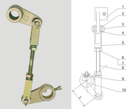
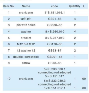
3. Connecting Rod Assembly
|
|
|


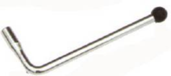
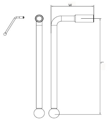
4. Operating Handle for Earthing Switch
|
Remark: The length and width of the handle can be designed according to customer requirement. |
|