Molded Case Circuit Breaker (MCCB)
1. General Introduction
M1 series plastic molded case circuit breakers (hereinafter referred to as circuit breakers) are new type of circuit breaker designed and developed using international advanced technology. The circuit breaker has a small volume, high breaking capacity, short flash arc, and anti vibration characteristics, suitable for use on land and ships Ideal product. The rated insulation voltage of the circuit breaker is 690V, applicable for AC 50Hz/60Hz, rated working voltage up to 660V, rated current up to 1250A in an electrical network. It is used to distribute electrical energy and protect circuits and power equipment from overload and short circuits damage caused by faults such as under-voltage. It can also be used for infrequent line switching and infrequent motor operation start and overload, short circuit, under-voltage protection.
The circuit breaker can be installed vertically (i.e. vertically) or horizontally (i.e. horizontally). The circuit breaker is suitable for isolation, and the symbol is "- Hx -". The circuit breaker complies with the standard GB 14048.2 "Low voltage switchgear and control equipment。
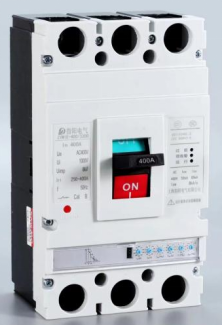
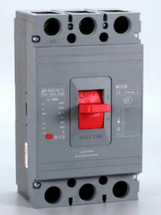
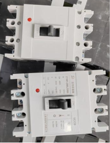
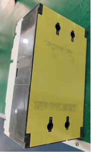
The photos of actual products are as following:
 |
 |
 |
 |
 |
|
 |
 |
2. Normal Service Conditions
2.1 The altitude of the installation site shall not exceed 2000m;
2.2 The ambient air temperature shall not exceed+40 ℃, and its average temperature value within 24 hours shall not exceed+35 ℃; The lower limit of ambient air temperature is -5 ℃;.
Note: If the ambient air temperature is above+40 ℃ or below -5 ℃, it should be adjusted accordingly Factory negotiation.
2.3 When the maximum temperature is+40 ℃, the relative humidity of the air does not exceed 50%, and at lower temperatures High humidity can be allowed at temperatures, such as up to 90% at 20 ℃. Due to temperature Special measures should be taken for occasional condensation on the product caused by changes.
2.4 The pollution level is Level 3.
2.5 The installation category of the main circuit of the 2.5 circuit breaker is III, and the auxiliary circuit that is not connected to the main circuit and The installation category of the control circuit is II;
2.6 The maximum inclination for installation is 22.5 °;
2.7 Reliable operation under normal vibration of the ship;
3. Major Technical Data
|
Model |
Rated current of the frame (A) |
Rated current In (A) |
Rated voltage (V) |
Poles |
Rated short-circuit breaking capacity (kA) |
Distance of flashing arc (mm) |
||||
|
Icu/cosΦ |
Ics/cosΦ |
|||||||||
|
380V |
660V |
380V |
660V |
|||||||
|
AM1-63L |
63 |
10, 16, 20, 25, 32, 40, 50, 63 |
380 |
3 |
25 |
- |
12.5 |
- |
<=50 |
|
|
AM1-63M |
3,4 |
50 |
- |
25 |
- |
|||||
|
AM1-63H |
3 |
85 |
- |
50 |
- |
|||||
|
AM1-125L |
125 |
16, 20, 25, 32, 40, 50, 63, 80, 100 |
380 |
2,3,4 |
35 |
- |
25 |
- |
||
|
AM1-125M |
380/660 |
2,3,4 |
50 |
10 |
25 |
5 |
||||
|
AM1-125H |
380 |
3,4 |
85 |
- |
45 |
- |
||||
|
AM1-250L |
250 |
100, 125, 160, 180, 200, 225, 250 |
380 |
2,3,4 |
35 |
- |
17.5 |
- |
||
|
AM1-250M |
380/660 |
2,3,4 |
50 |
10 |
25 |
5 |
||||
|
AM1-250H |
380 |
3,4 |
85 |
- |
50 |
- |
||||
|
AM1-400L |
400 |
225, 250, 315, 350, 400 |
380/660 |
3,4 |
50 |
10 |
25 |
5 |
<=100 |
|
|
AM1-400M |
3,4 |
65 |
10 |
32.5 |
5 |
|||||
|
AM1-400H |
380 |
3,4 |
100 |
- |
55 |
- |
||||
|
AM1-630L |
630 |
400, 500, 630 |
380 |
3,4 |
50 |
- |
25 |
- |
||
|
AM1-630M |
380/660 |
3,4 |
65 |
10 |
32.5 |
5 |
||||
|
AM1-630H |
380 |
3,4 |
100 |
- |
60 |
- |
||||
|
AM1-800M |
800 |
630, 700, 800 |
380/660 |
3,4 |
65 |
20 |
42 |
10 |
||
|
AM1-800H |
380 |
3,4 |
100 |
- |
60 |
- |
||||
|
AM1-1250H |
1250 |
700, 800, 1000, 1250 |
380/660 |
3,4 |
65 |
20 |
35 |
10 |
||
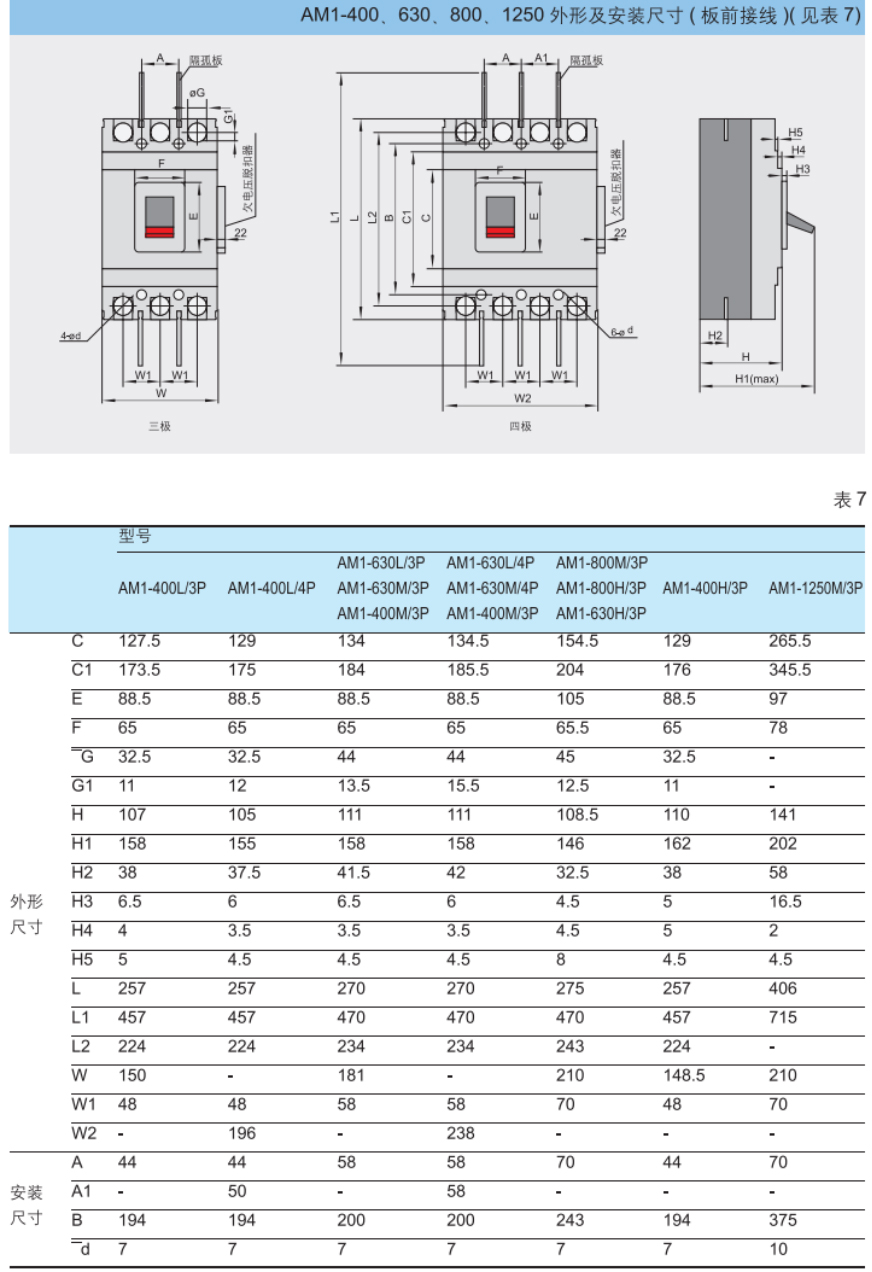
4. Dimensions of AM1-63L/100L/250L

Dimensions of AM1-400L/630L/800L/1250L